
Keywords: Iran power grid imbalance, solar power plants, quality health testing, EL report, I–V curve, PID report
1. Introduction
With the growing imbalance between electricity generation and consumption in Iran and the decreasing accessibility of fossil resources, the development of renewable energy—particularly solar power plants—has become one of the main priorities of the national electricity industry. Iran’s climatic conditions, including high solar irradiation across most regions, provide favorable capacity for sustainable clean energy generation. However, the performance and efficiency of solar power plants are highly dependent on the quality and health of the equipment used.
In the design and construction process of solar power plants, the proper technical selection of core equipment—such as solar panels, inverters, and high-voltage substations—plays a critical role in achieving stable and cost-effective operation. Ensuring the integrity and longevity of this equipment requires specialized pre-purchase testing, as the presence of microscopic cracks or hidden defects in solar panels can lead, within a short operational period, to issues such as hot spots, power degradation, and even system shutdown. These failures not only have technical implications but also cause substantial financial losses for investors. Therefore, conducting detailed equipment evaluations prior to purchase is essential to minimize operational and economic risks.
At the international level, standards such as IEC 61215, IEC 61730, and IEC 62804 are recognized as the main references for performance and safety testing of photovoltaic (PV) modules. These standards define a series of tests—including EL imaging, I–V curve measurement, PID testing, and Damp Heat testing—to assess the durability and quality of solar panels. However, in many domestic projects, comprehensive implementation of these tests during the pre-purchase phase is often neglected.
The objective of this paper is to introduce and analyze a set of technical and standardized tests to ensure the health of solar equipment prior to purchase. Accordingly, key tests such as EL, I–V, and Hot Spot, along with complementary evaluations related to PID, Damp Heat, Humidity Freeze, Water Spray, and IP, are discussed in detail. The results of this study can serve as a reliable technical guide for engineers, contractors, and investors during the evaluation and selection process of solar equipment.
2. Essential Tests for Evaluating Solar Equipment Health
This section examines the key tests necessary to ensure the operational integrity of solar modules prior to purchase.
2.1. Electroluminescence (EL) Testing – Detection of Micro-Cracks
2.1.1. Overview and General Description
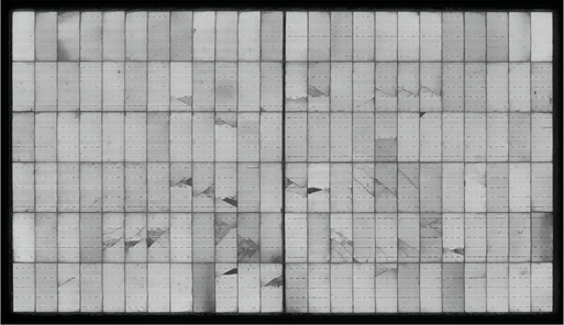
Electroluminescence (EL) is a phenomenon in which photovoltaic (PV) cells emit infrared or visible light when an electric current passes through the module—similar to extremely low-intensity LEDs. In EL images, inactive or shunted regions appear dark, while micro-cracks typically manifest as thin dark lines or spots. Due to its high sensitivity, EL imaging provides significantly more detailed defect detection than visual inspection and can reveal hidden issues that are not visible to the naked eye.
Figure (1) illustrates an example of EL imaging results.
2.1.2. Objectives and Procedure of the EL Test
The primary objective of the Electroluminescence (EL) report is to identify and document the location, type, and severity of micro-cracks within photovoltaic (PV) modules. Additionally, the percentage of the affected surface area or regions with reduced electrical activity must be determined in order to estimate the potential risk of power loss. Moreover, EL test results serve as technical evidence for shipment acceptance or rejection, and may be used to request warranty claims or replacement from the manufacturer.
Each EL test report must include the following details:
Report identification code, date, location, laboratory name, and operator’s name.
Module specifications: manufacturer, model, serial number, production date, and official datasheet parameters of the tested panel.
Test conditions, including test type, environmental conditions, camera type, lens specifications, etc.
Final EL images.
Comprehensive analysis, including defect type, location, severity, and damage percentage.
Official client signature and reference to the applicable standard; the primary reference for this test is IEC TS 60904-13.
The general procedure for conducting the EL test is as follows:
Dark Environment:
EL imaging must be carried out in complete darkness, as even minimal ambient light can cause optical noise and reduce image contrast. For precise results, the test is typically performed inside a dark, non-reflective chamber or outdoors at night under zero ambient light. The module surface must be clean and free of dust, water stains, oil, or fingerprints, as surface contamination may absorb or scatter light, altering the luminance pattern in the EL image. A clean surface not only minimizes imaging noise but also significantly enhances the visibility of cracks and the distinction between active and inactive areas.Electrical Activation:
After preparing the environment, the tested module must be connected to an appropriate electrical power source to establish current flow within the cells. In the EL method, either reverse current or forward bias is applied, causing the cells to emit light similarly to diodes in luminescent mode. Typically, testing is performed under one of the following two conditions:Short-Pulse Current Mode: The nominal module current is momentarily applied to fully excite the active regions of the cells, producing a uniform emission pattern.
Constant DC Bias Mode: In some cases, instead of short pulses, a steady DC current or voltage—typically between 70% to 100% of nominal values—is applied. This approach allows for better image comparability and more precise control of test parameters.
The choice between biasing methods should depend on module design and test objectives. All parameters—current or voltage levels, duration, module temperature, polarity, and power source type—must be accurately documented in the report.
Imaging Setup:
Since the emitted luminescence is extremely weak, near-infrared (NIR/ Near-infrared) sensitive cameras are required. The two most common sensor types are:Si-CCD cameras, suitable for wavelengths up to approximately 1100 nm, commonly used for silicon-based cells.
InGaAs cameras, capable of detecting longer wavelengths (1000–1700 nm), particularly used for CIGS or GaAs cell technologies.
Camera Calibration:
The camera’s optical axis should be perfectly perpendicular to the module surface to minimize viewing distortion and brightness variation at the edges. Key camera parameters—exposure time, gain, pixel binning (to reduce noise and enhance sensitivity), and optical filter type—must be optimized according to the emission intensity and cell type, and recorded in the EL report.
Typically, the exposure time ranges from a few hundred milliseconds to several seconds to ensure that the weak luminescent signal is properly captured.
Full-Frame Imaging:
Next, full-frame images of the sample are captured. If any suspicious areas are detected, zoomed-in imaging is performed on those specific regions. Typically, multiple frames are taken for each area, and an averaging process is applied to minimize image noise and improve clarity.Image Processing and Analysis:
In the following step, the captured images undergo post-processing and analysis, which includes contrast adjustment, brightness gradient correction, thresholding, and detection of dark regions. In many modern laboratories, this stage is performed using automated software or machine learning algorithms designed to identify and classify micro-cracks with high precision.Test Result Classification:
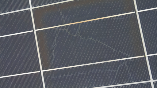
Upon completion of testing and image finalization, EL test results are generally categorized into the following classes:Class A (Acceptable): No significant cracks are present, or only very minor cracks (covering less than 1–2% of the cell surface) are detected, which have no measurable impact on performance.
Class B (Moderate Defect): Cracks have rendered parts of the cell inactive, affecting approximately 2–10% of the surface area. In this case, additional tests, such as I–V curve measurement and Infrared (IR) thermography, are required to accurately estimate power loss and assess insulation performance.
Class C (Unacceptable): Cracks are widespread or have caused cell fracture, impacting more than 10% of the surface area. Under these conditions, there is a high risk of crack propagation and severe power loss, rendering the panel unfit for use.
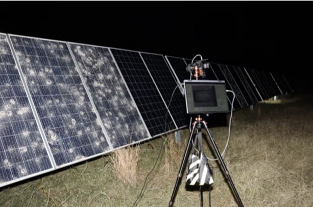
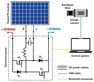
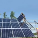
Photo(2) presents an example of EL testing performed on solar panels under real field conditions, while Photo(3) shows the electrical circuit configuration used during the EL test.
2.2. I–V Test
2.2.1. Introduction and General Overview
The I–V (Current–Voltage) curve represents the relationship between the output current (I) and output voltage (V) of a solar cell, module, or array under specific irradiance and temperature conditions. In other words, this curve provides a graphical illustration of how a solar panel performs under real operating conditions.
From the I–V curve, key performance parameters can be extracted, including:
Short-circuit current (Isc)
Open-circuit voltage (Voc)
Current at maximum power (Imp)
Voltage at maximum power (Vmp)
Maximum power output (Pmax)
Efficiency (ƞ)
Comparing the measured I–V curve with the reference curve provided in the manufacturer’s datasheet is an essential step for verifying performance, identifying potential defects, and validating shipment conformity.
The most commonly used equipment for measuring the I–V characteristics of solar modules includes:
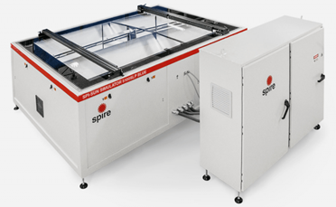
Flash Tester:
These devices are typically used in laboratories or production lines. Their function is to generate a short-duration, high-intensity light pulse that simulates sunlight under Standard Test Conditions (STC). When the module is exposed to this pulse, its I–V curve and maximum power (Pmax) can be recorded almost instantly. Flash testers are mainly employed in factory quality control and rapid performance verification of solar modules.
Photo(4) illustrates an example of a Flash Tester device used for I–V characterization.
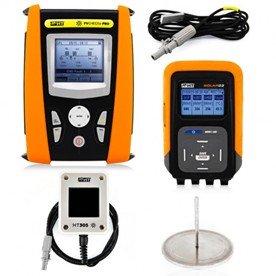
I–V Curve Tracker:
These devices are portable and designed for direct on-site measurements on installed modules, whether on rooftops or ground-mounted arrays. They vary the electrical load and record the complete current–voltage (I–V) curve. For enhanced accuracy, they are typically used in conjunction with two critical sensors.A high-end example of this category is the PVCHECKs-PRO system. Its associated sensors, HT305 and Solar03, measure ambient temperature and solar irradiance, respectively, ensuring precise I–V characterization.
Photo (5) also shows the PVCHECKs-PRO system along with its HT305 and Solar03 sensors.
2.2.2. I–V Test Procedure
The I–V curve can be measured in two main ways: laboratory testing using a Flash Tester and field testing using the PVCHECKs-PRO device. The detailed procedures for both methods are as follows:
Laboratory Testing (Flash Tester):
The module is first mounted on the tester holder. The device then applies a short, high-intensity light pulse of approximately 1000 W/m², simulating Standard Test Conditions (STC). During this pulse, the I–V curve is recorded, and key parameters such as Isc, Voc, Imp, Vmp, Pmax, and efficiency (ƞ) are extracted. The module’s temperature is measured during or after the pulse, and all test parameters are documented. Finally, the measured data are compared with the manufacturer’s datasheet, and results are reported according to contractual acceptance criteria.Field Testing (PVCHECKs-PRO):
The test is conducted under natural sunlight, and timing is critical. Ideally, the irradiance should be stable and between 500–800 W/m² (preferably close to 1000 W/m²) with a stable sun angle and clear sky conditions. Before testing, the module surface must be clean, adequate ventilation ensured, and shading avoided. Reference sensors for irradiance and module backside temperature are installed. The PVCHECKs-PRO device then measures and records the complete I–V curve in real operational conditions.
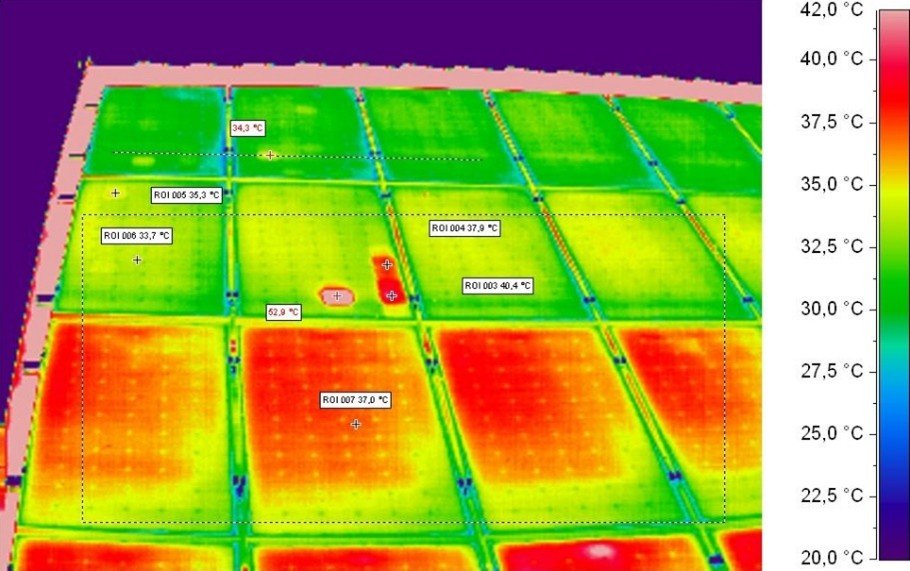
2.3. Hot Spot Testing / Thermal Imaging
2.3.1. Introduction and Overview
Hot Spot testing uses infrared (IR) cameras to identify areas on the module surface with abnormal temperatures. Cells or portions of the module that exhibit unusual current or resistance generate more heat, appearing as hot spots in the thermal image. These hot spots can result from micro-cracks, internal shunts, partial shading, or weak electrical connections.
The primary objectives of this test are:
Detect hot spots to prevent cell damage, efficiency loss, and potential fire hazards.
Identify functional defects, such as defective cells, high series resistance, or poor interconnections.
Support pre-purchase quality control, as well as long-term monitoring and maintenance, to identify modules requiring repair or replacement.
2.3.2. Testing Conditions and Procedure
Common equipment and tools for Hot Spot testing include:
High-sensitivity infrared camera (temperature resolution ~0.5–1°C).
Thermal analysis software for marking and evaluating problematic areas.
Tripod or mounting stand for camera stabilization.
Surface thermometer or reference temperature sensor (optional for calibration).
The procedure consists of the following steps:
Select optimal testing time and conditions:
For field tests, irradiance should be at least 500 W/m², and the sun angle should be nearly optimal relative to the module surface.
In laboratory settings, a solar simulator or artificial load can be used.
Prepare the module surface: Clean thoroughly, as dust or moisture may distort IR images.
Position the IR camera at an appropriate angle to cover the entire module surface.
Perform the test under real operating conditions (connected to load or grid) and capture thermal images.
Image analysis: Areas with temperatures 5–10°C higher than healthy cells are identified as hot spots. Thermal software can measure peak temperature, temperature distribution, and the area of concern.
Documentation: Raw and analyzed IR images, module serial number, test conditions, irradiance, temperature, and any identified issues are fully recorded for reporting.
Interpretation of Results:
The significance of hot spots depends on their severity and extent. Small or mild hot spots may have minimal impact on module power output but should be monitored regularly. Extensive or severe hot spots can lead to reduced maximum power, cell damage, and even fire hazards, and typically require module replacement.Linear or grid-like hot patterns in thermal images may indicate micro-cracks or sequential cell failures. Additionally, abnormal heat near the junction box may result from a faulty bypass diode or a loose electrical connection.
Image (6) shows an example of the Hot Spot test results.
3. Auxiliary and Complementary Tests for Solar Panel Health Assessment
In Section 2, we covered the essential and primary tests for evaluating the health of solar panels prior to purchase. Section 3 introduces additional and complementary tests that further ensure panel reliability and long-term performance.
3.1. PID (Potential-Induced Degradation) Testing
3.1.1. Concepts and Overview
PID (Polarization-Induced Degradation) refers to the phenomenon where a potential difference between the active circuit of solar cells and the module frame or ground causes a leakage current. This leakage current can induce ion migration within the module structure, gradually reducing its performance.
Effects of PID include:
Reduction in module power output
Increase in shunt current (equivalent to decreased shunt resistance)
Formation of hot spots or degradation of internal module layers
In other words, PID is a process that can gradually lower performance and shorten the operational lifespan of Aiko solar panels, making it a critical consideration in system design and maintenance.
PID testing identifies modules that may experience performance loss under real-site conditions such as high system voltage, humidity, and temperature. Conducting PID tests enables manufacturers and users to:
Avoid accepting PID-sensitive modules, which may experience significant power loss within the first months or year of operation.
Document module behavior under voltage stress, which is crucial for warranty claims and selection of more robust materials and technologies.
In summary, PID testing acts as a preventive and quality-assurance tool to guarantee long-term module performance.
3.1.2. Common Methods and Test Conditions
A widely used laboratory protocol, often referred to as “PID 96h”, typically involves:
Temperature of approximately 60°C (some protocols specify up to 85°C)
Relative humidity around 85%
Bias voltage applied equal to the nominal system voltage or a reference voltage depending on the test conditions
Test duration of 96 hours, serving as a standard initial protocol, although IEC TS 62804 defines various stress levels and conditions
Common PID testing methods include:
Chamber Method (IEC TS 62804-1):
Record module specifications and measure the initial I–V curve.
Place the module in a climate chamber and adjust temperature and humidity according to protocol.
Apply DC voltage between the module circuit and frame/ground for a specified period.
Measure leakage current during or at the end of the test and record changes.
Re-measure the I–V curve after the test and compare it to the initial measurement.
Prepare a report summarizing power loss percentage and test result (pass/fail or sensitivity rating).
Conductive Foil Method:
Instead of a climate chamber, a layer of water or conductive foil is placed on the module glass to create a leakage path. DC bias is applied, and module behavior under humid conditions is evaluated. This method is suitable for field testing or faster assessments and is also referenced in IEC TS 62804.
3.2. Damp Heat Testing
One of the most important tests for evaluating durability and performance of solar panels is the Damp Heat test, which examines panel resistance to harsh environmental conditions, particularly in hot and humid regions. This test simulates long-term exposure to elevated temperature and humidity to assess material stability, encapsulant integrity, and overall module reliability.
3.3. Damp Heat Testing
In this test, conditions simulating hot and humid environments are applied to assess the long-term performance and stability of solar panels. According to international standards IEC 61215 and IEC 61730, the panel is exposed to approximately 85°C with 85% relative humidity. The standard test duration is typically 1000 hours, although advanced tests may extend this period to evaluate long-term degradation effects more precisely.
The primary goal of Damp Heat testing is to evaluate the panel’s resistance to prolonged exposure to heat and humidity. After the test, the panel is examined for:
Degradation of protective layers
Reduction in power output
Changes in electrical characteristics
Any physical or chemical damage
These results help determine whether the panel can withstand harsh environmental conditions and allow manufacturers to identify and improve design weaknesses or materials.
3.4. Humidity Freeze Testing
The Humidity Freeze Test, conducted according to IEC 61215, evaluates module durability under rapid and extreme temperature and humidity changes, reflecting real-world conditions in variable climates.
Test procedure:
Modules are exposed to high temperature and humidity conditions (typically 85°C and 85% RH).
Temperature is then rapidly lowered to around -40°C to simulate freezing conditions.
This cycle is repeated multiple times, usually 10 full cycles, to ensure structural and functional stability.
During the test, modules are inspected for:
Glass cracking
Delamination or failure of internal layers
Water ingress into cells or circuitry
The results indicate whether the module can maintain performance and meet its designed lifespan under extreme environmental stress, making this test a critical step in quality assessment.
3.5. Water Spray and IP Testing
These tests assess the water resistance of the module frame and junction box, essential for outdoor operation where modules are exposed to rain, dew, humidity, or surface cleaning. Any failure in sealing may lead to:
Corrosion
Short circuits
Electrical performance loss
Complete module failure
International IP standards define protection levels:
IP65: Protection against water jets from any direction, with no water ingress.
IP67: Temporary immersion in water to evaluate sealing under harsher conditions.
The main objective is to ensure complete water tightness and long-term durability, confirming that the module can operate safely in various outdoor environments, from humid to rainy or snowy conditions.
4. Conclusion
This report demonstrates that conducting technical and standard tests on solar panels before purchase plays a crucial role in ensuring stable performance, long service life, and economic efficiency of solar power plants.
Key functional tests such as Electroluminescence (EL), I–V curve, and Hot Spot testing are effective for detecting hidden defects in cells and modules, including micro-cracks, inactive areas, or thermal irregularities, preventing early power loss or premature failure.
Complementary environmental tests—including PID, Damp Heat, Humidity Freeze, and Water Spray/IP testing—assess module resilience against humidity, high temperatures, electrical stress, and water ingress, providing a scientific basis for predicting long-term performance.
Overall, establishing a pre-purchase quality assessment process based on these tests ensures:
Technical integrity of solar panels
Reduced operational power loss
Increased economic returns for solar projects
Adhering to these protocols is a fundamental step to secure sustainable energy production and protect investment in renewable energy projects.
About Steelbridge Export
Steelbridge Export is a trusted supplier and partner in the renewable energy sector, specializing in high-quality solar equipment and turnkey solar solutions. With a strong commitment to reliability, technical expertise, and global sourcing, Steelbridge Export ensures that every solar module, inverter, and accessory meets international standards for performance, durability, and safety. The company supports investors, contractors, and energy developers in achieving efficient, sustainable, and economically viable solar power projects.
Related Articles: What Is Microluminescence Report? Why Is EL Report So Important?
Frequently Asked Questions (FAQs)
1. Why is EL (Electroluminescence) testing considered the most critical pre-purchase assessment?
EL testing is vital because it identifies micro-cracks, inactive regions, and manufacturing defects that are impossible to see visually.5 If these defects are not caught early, they can expand into “dead zones,” leading to significant power degradation and the development of dangerous Hot Spots over time.
2. How does the I–V curve test protect a solar investor?
The I–V curve test measures the actual current and voltage relationship under specific irradiance. It verifies key parameters like $P_{max}$ (Maximum Power) and Efficiency. This ensures the buyer is getting exactly what they paid for and that the shipment meets the official datasheet specifications.
3. What is Potential-Induced Degradation (PID) and why should I test for it?
PID is a phenomenon where leakage currents cause ion migration, leading to a rapid loss in panel performance.6 Testing for PID sensitivity ensures that the modules will not lose significant power within the first few years of operation when exposed to high system voltages and humidity.
4. Can Hot Spot testing prevent fires in solar installations?
Yes. Hot Spot testing using infrared (IR) cameras identifies cells that are overheating due to internal shunts or cracks. By rejecting panels with significant thermal irregularities, you eliminate the primary cause of cell melting and potential fire hazards in the field.
5. What do IP65 and IP67 ratings mean for panel longevity?
These Ingress Protection (IP) ratings ensure that the junction box and frame are perfectly sealed against dust and water.7 A high IP rating is essential for outdoor operation, preventing corrosion and short circuits caused by rain, dew, or cleaning processes.8
Introduction Summary
As solar power plants expand rapidly in high-irradiation regions like Iran, ensuring the quality of core equipment has become a top priority for investors. This paper highlights that visual inspection is insufficient for high-stakes projects. By implementing a rigorous testing regime—including Electroluminescence (EL), I–V curve tracing, and thermal imaging—engineers can detect hidden micro-cracks and performance gaps before the panels are even purchased. Adhering to international standards such as IEC 61215 and IEC 61730 ensures that the solar modules can withstand harsh environmental conditions (heat, humidity, and dust) for over 25 years, protecting both the technical integrity and the financial viability of the energy project.
Call to Action (CTA)
Don’t gamble with your solar plant’s future! Before you sign your next procurement contract, ensure your modules are certified through rigorous pre-purchase health assessments. Contact Steelbridge Export today for expert technical consulting and access to high-performance, fully tested solar equipment.


2 Comments
Can you be more specific about the content of your article? After reading it, I still have some doubts. Hope you can help me.
Hello Dear Reader,
Let me know what your doubts are and i will help you by asking our technical team.